

Micro plastic parts may contain less material than conventional mouldings, but they are rarely simpler to manufacture. Small flow passages, fine features, rapid heat transfer and limited space for gating and ejection make seemingly minor design decisions important to tooling feasibility and production consistency.
Academic reviews of micro injection moulding emphasise the close relationship between part geometry, polymer behaviour, tooling, process conditions and feature replication. This means that manufacturability should be reviewed while the design can still be changed, not after the mould has been built.
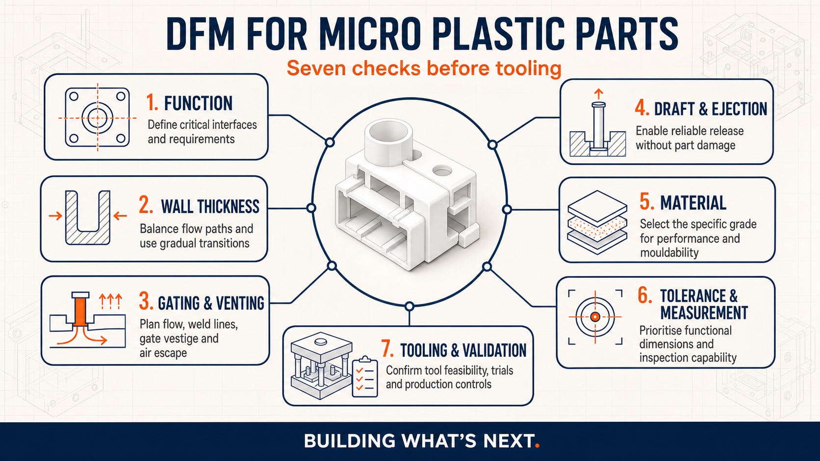
The following checklist gives design engineers a practical framework for reviewing a micro plastic component with their moulding partner before releasing it for tooling.
1. Define the critical requirements first
A useful DFM review begins with the function of the component, not with a general examination of its CAD model.
Identify which features affect fit, sealing, electrical performance, optical performance, fluid flow or another essential function. Separate these critical features from dimensions that are not functionally sensitive. Also establish the intended operating environment, assembly method, production volume, cosmetic expectations and applicable regulatory requirements.
Ask:
- Which dimensions directly affect product performance?
- Which surfaces interface with another component?
- Which features require traceability or inspection?
- What constitutes an acceptable part?
- How will each critical requirement be measured?
This prevents the toolmaker and moulder from treating every drawing dimension as equally important. It also provides the basis for sensible tolerance allocation and an appropriate validation plan.
2. Review wall thickness and transitions
Consistent wall thickness generally supports more predictable filling, packing and cooling. In a micro component, a relatively small geometric transition can become a significant restriction in the flow path.
Review the model for abrupt changes between thick and thin sections, locally heavy features, isolated masses of material and narrow flow passages. Where the product permits, use gradual transitions and consider whether strength can be achieved through geometry rather than simply adding material.
The objective is not to impose one universal wall-thickness rule. The feasible geometry depends on the selected polymer, flow length, tool temperature, gate arrangement, surface requirements and moulding process.
Ask:
- Does the melt have a continuous and balanced path through the part?
- Could a thin section freeze before the remaining cavity is filled?
- Are there local accumulations of material that may cool differently?
- Can a heavy feature be cored, relieved or redesigned?
- Have wall transitions been reviewed together with the proposed material?
For complex components, flow analysis can help identify risk, but its assumptions should be reviewed by the moulding team and supported by actual trials.
3. Treat gate location as a product-design decision
The gate is not merely a tooling detail. Its position can affect filling direction, pressure transfer, weld-line location, orientation, appearance and the residual gate vestige.
Micro parts provide little room for a gate, and the most convenient tooling location may not be the best functional location. Gate design must consider how the polymer reaches critical features and whether air can escape as the cavity fills.
Ask:
- Will the proposed gate allow the critical features to fill reliably?
- Where are flow fronts likely to meet?
- Could a weld line form across a loaded or sealing feature?
- Is the gate located on an acceptable cosmetic surface?
- Can the gate be removed without damaging or distorting the part?
- Will the gate arrangement support the intended level of automation?
- Is there a suitable route for venting displaced air?
The gate, runner, cavity and venting strategy should therefore be reviewed as one system. Moving the gate after tooling has begun may involve more than a local modification.
4. Provide for draft and controlled ejection
Vertical surfaces can resist release from the mould, particularly when they are deep, textured or located around fine cores. A component that fills correctly but cannot be ejected consistently is not production-ready.
Add draft wherever the function allows. The appropriate draft depends on feature depth, surface finish, polymer shrinkage, tool construction and the direction in which the part will leave the mould. A generic value should not be applied without considering these factors.
Ask:
- Has the intended mould-opening direction been defined?
- Which surfaces may grip a core during cooling?
- Are any textures or fine features working against ejection?
- Is there enough robust surface area to apply ejection force?
- Could ejector contact damage a functional or cosmetic feature?
- Will the part remain on the intended side of the mould when it opens?
Ejection should be considered early because it can influence wall geometry, parting lines, core construction and the visible surfaces of the finished component.
5. Select a specific material grade, not only a polymer family
Material selection should balance product performance with mouldability. Mechanical strength, temperature resistance, chemical compatibility, electrical behaviour, biocompatibility or optical properties may narrow the options, but the chosen grade must also fill and replicate the proposed geometry.
Micro-scale flow can behave differently from conventional moulding because of the component’s surface-to-volume relationship and rapid heat transfer. Published research on micro injection moulding highlights the importance of polymer rheology, mould temperature, melt temperature and feature geometry in replication quality.
Review:
- Flow behaviour in the proposed geometry
- Shrinkage and dimensional stability
- Moisture sensitivity and drying requirements
- Thermal stability and allowable residence conditions
- The effect of fillers or reinforcement on fine features
- Required surface finish or optical performance
- Regulatory, traceability and documentation requirements
- Commercial availability and long-term supply
Approve the actual commercial grade wherever possible. Two grades within the same polymer family may not process or shrink identically.
6. Build a functional tolerance stack-up
Applying very tight tolerances to every dimension does not automatically produce a better component. It can increase tooling complexity, inspection effort and rejection risk without improving product performance.
Start with the assembly or functional requirement and work backwards through the contributing dimensions. Establish a logical datum structure and distinguish between dimensions formed within the same tool feature and dimensions influenced by different mould elements, parting lines, inserts or moving actions.
Ask:
- Which dimensions form the functional stack?
- Are all specified tolerances necessary for function?
- Does the datum system reflect how the part will be assembled and inspected?
- How will polymer shrinkage and process variation affect the stack?
- Can an interface be redesigned to accommodate expected variation?
- Is the proposed measurement method capable of resolving the requirement?
ISO 20457 provides a recognised framework for tolerances and acceptance conditions for plastic moulded parts. It should be applied alongside product-specific requirements, measurement capability and agreement between the designer and manufacturer, rather than treated as a substitute for engineering judgement.
7. Check whether the tool and measurement method can reproduce the drawing
Every small feature in the part requires a corresponding feature in the mould. Fine slots, pins, ribs, undercuts and sharp internal geometry may create fragile or difficult-to-manufacture tool elements.
Review whether the proposed tool features can be manufactured, finished, vented, inspected, maintained and, when necessary, replaced. Provide reasonable radii where the function permits and avoid creating tool steel conditions that are unnecessarily weak.
Measurement should be reviewed at the same time. A tolerance has limited practical value if the feature cannot be located, fixtured and measured repeatably. Confirm the inspection method for critical dimensions before finalising the drawing.
Final release checklist
Before releasing a micro plastic component for tooling, confirm that:
- Critical functional features have been identified.
- Wall thickness and transitions have been reviewed with the proposed material.
- Gate location, flow direction, weld lines and venting have been assessed.
- Draft, mould opening and ejection have been considered.
- A specific commercial material grade has been selected or shortlisted.
- Functional tolerances have been separated from non-critical dimensions.
- The datum structure supports assembly and inspection.
- Fine tool features can be manufactured and maintained.
- Measurement methods are defined for critical requirements.
- The design, tooling, quality and production teams have reviewed the same revision.
DFM works best as an early collaboration
The greatest value of a DFM review comes before the design is frozen. At that stage, the product designer, toolmaker and moulder can balance function, material behaviour, tooling constraints, inspection and production requirements without relying on costly corrective work later.
Plast Plastics supports customers with micro moulding, tooling and mould maintenance, and quality and precision measurement.
If you are developing a miniature plastic component, send us your drawing, material requirements and expected application through our request-a-quote page. An early manufacturability review can help identify the right questions before tooling begins.
Technical references and further reading
- ISO, ISO 20457:2018, Plastics moulded parts: Tolerances and acceptance conditions. The edition was reviewed and confirmed in 2024.
- Loaldi et al., A Review of Microinjection Moulding of Polymeric Micro Devices, Micromachines. This open-access review examines relationships among machinery, process conditions, rheology, tooling, replication and material properties.
- Giboz, Copponnex and Mélé, Microinjection molding of thermoplastic polymers: A review, Polymer Engineering & Science. This paper compares micro injection moulding with conventional injection moulding and reviews materials, tooling and process considerations.
- Sha et al., Investigation of micro-injection moulding: Factors affecting the replication quality, Journal of Materials Processing Technology. The research examines how processing conditions affect micro-feature replication.