Tooling risk is highest not during full production, but in the weeks before it. Once a production mould is cut, changes to gate location, wall thickness or core geometry become slow and expensive to make. Reducing that risk means front-loading validation work: reviewing the design for manufacturability, simulating how the material will fill the tool, proving the concept with prototype tooling, and inspecting the first parts rigorously before ramp-up begins.
Why Tooling Risk Rises Sharply Once Steel Is Cut
The economics of tooling change are well documented in manufacturing literature. An analysis published in Plastics Engineering, the Society of Plastics Engineers' journal, tracked a real product programme and found that the cost of a design error and change increases exponentially the later it occurs in the development lifecycle. In the case study, each engineering change made to the tool after it had been cut cost an average of several thousand dollars per change, and the resulting schedule slip contributed to a significant loss in forecast revenue. The specific figures will not apply to every programme, but the underlying pattern holds across the industry: a correction that costs little on a CAD model can cost a great deal once it requires reworking hardened steel.
This is the reason tooling risk reduction is best treated as a sequence of checkpoints, each intended to catch a different category of problem before it reaches the tool.
Start with a Structured DFM Review
A design for manufacturability (DFM) review checks the part geometry against what the moulding process can reliably achieve. Typical areas of focus include wall thickness uniformity, draft angles, rib and boss proportions, undercuts that will require mould actions, and gate placement relative to critical dimensions. Issues found here are usually resolved with a model change rather than a tooling change, which is the cheapest point in the process to make a correction.
For components with tight tolerances or cosmetic requirements, it is worth confirming early which features are truly critical to function and which have flexibility, since this shapes decisions later in tool design.
Learn more about our injection moulding capability.
Validate Flow Behaviour with Mould Flow Analysis
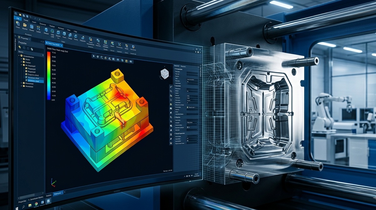
Mould flow analysis is a simulation technique that models how molten resin will move through the cavity before any tool steel is machined. It helps identify likely short shots, weld line locations, sink marks and pressure imbalances between cavities, and supports decisions on gate position, runner layout and wall thickness. Industry guidance from mould-flow practitioners notes that running this analysis is faster and less expensive than machining tooling, running sample parts, and then modifying the tool after the fact, and that visualising flow patterns, pressure points and weld lines before physical tooling exists allows engineers to proactively optimise the design and cut development costs.
Flow analysis will not catch every issue a physical trial reveals, but it substantially narrows the range of surprises that show up once the tool is running.
Prove the Concept with Prototype or Bridge Tooling
For parts with meaningful geometric or material risk, a prototype or bridge tool, a lower-cost, lower-cycle-life tool built from softer steel or aluminium, allows the design to be validated in the actual moulding process before committing to a hardened production tool. This step is particularly valuable where the flow simulation flagged marginal areas, where the material has not previously been run in a similar geometry, or where downstream assembly and fit need to be physically confirmed rather than assumed from a model.
See our tooling and mould maintenance capability.
Confirm Conformance with First Article Inspection
Before scaling production, the first parts off a tool should be measured against every dimension on the approved drawing, not just the features assumed to be critical. This practice is formalised in the aerospace industry through SAE's AS9102 standard, whose stated purpose is to provide objective evidence that all engineering design and specification requirements are properly understood, accounted for, verified, and documented. Even outside aerospace, applying the same discipline, measuring every printed dimension on a representative sample and recording the results, gives an objective baseline for whether the tool is producing conforming parts before volume production begins.
A comparable logic underpins the automotive industry's Production Part Approval Process (PPAP), which exists to provide evidence that the customer engineering design record and specification requirements are clearly understood and fulfilled by the supplier, and to demonstrate that the manufacturing process can consistently meet requirements at the quoted production rate.
Learn more about our quality and precision measurement capability.
Control Changes Through Ramp-Up
Even with strong upfront validation, some changes will still be needed once volume trials begin. What separates controlled tooling risk from uncontrolled risk is whether those changes are documented, approved and traceable. A basic change control checklist should include:
- A formal engineering change request, describing the change and its reason
- Documented approval from both the design owner and the manufacturer before the tool is touched
- An updated first article inspection after any change that affects fit, form or function
- A revision log tying each tool modification to a specific part revision
A Practical Sequence for Reducing Tooling Risk
- Complete a DFM review before the design is frozen
- Run mould flow analysis to validate gating, wall thickness and cooling assumptions
- Where risk is meaningful, prove the design with prototype or bridge tooling
- Conduct a full first article inspection against the approved drawing
- Apply documented change control for any modification made after tool build
Conclusion
Tooling risk is rarely eliminated entirely, but it is highly manageable when validation happens in the right order and at the right stage. A structured DFM review, mould flow analysis, prototype tooling where warranted, disciplined first article inspection and documented change control together reduce the likelihood of the costly, late-stage surprises that delay production ramp-up.
If you are evaluating a precision plastic component and want to reduce tooling risk before committing to a production mould, Plast Plastics can review your drawings, design intent and manufacturing considerations. Contact our Singapore engineering and manufacturing team to discuss your project.
Sources and Further Reading
- Society of Plastics Engineers, "Eye-opening Impact of Simple Design Errors on Product Costs," Plastics Engineering, 2016. https://read.nxtbook.com/wiley/plasticsengineering/october2016/productdesign_eyeopeningimpact.html - supports the statement that design and tooling change costs rise exponentially later in development.
- Fictiv, "Mold Flow Analysis in Injection Molding: Optimizing the Process," 2025. https://www.fictiv.com/articles/moldflow-analysis-in-injection-molding - supports the explanation of what mould flow analysis is and why it is run before tooling.
- Pexco, "Mold Flow Analysis," 2026. https://www.pexco.com/news-and-events/mold-flow-analysis/ - supports the description of mould flow analysis identifying flow patterns, pressure points and weld lines before physical tooling.
- SAE International standard AS9102, summarised via AS9120 Store, "What is AS9102 First Article Inspection?" https://as9120store.com/aerospace-standards-explained/what-is-as9102-first-article-inspection/ - supports the definition and purpose of first article inspection.
- Automotive Industry Action Group (AIAG) Production Part Approval Process, summarised via Wikipedia, "Production part approval process." https://en.wikipedia.org/wiki/Production_part_approval_process - supports the description of PPAP's purpose in verifying supplier design and process conformance.